Ic 555 Timer Circuit Diagram. If you are wondering how the above simple timer circuits could be used for triggering a high power load through relay switching, then the following diagram will help you. It is a versatile IC and can be used to build a lot of applications due to which it is very popular among the electronic design engineers, workers, students.
It's a simple source of oscillating It includes all of the wiring diagrams and instructions you need to get started.
It is a versatile IC and can be used to build a lot of applications due to which it is very popular among the electronic design engineers, workers, students.
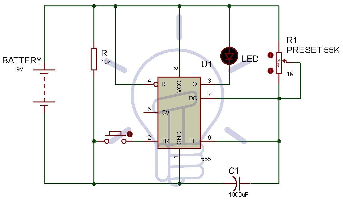
1 to 15 Minute Timer Circuit Diagram, Working and Applications
555 timer circuit diagrams | different modes of 555 timer

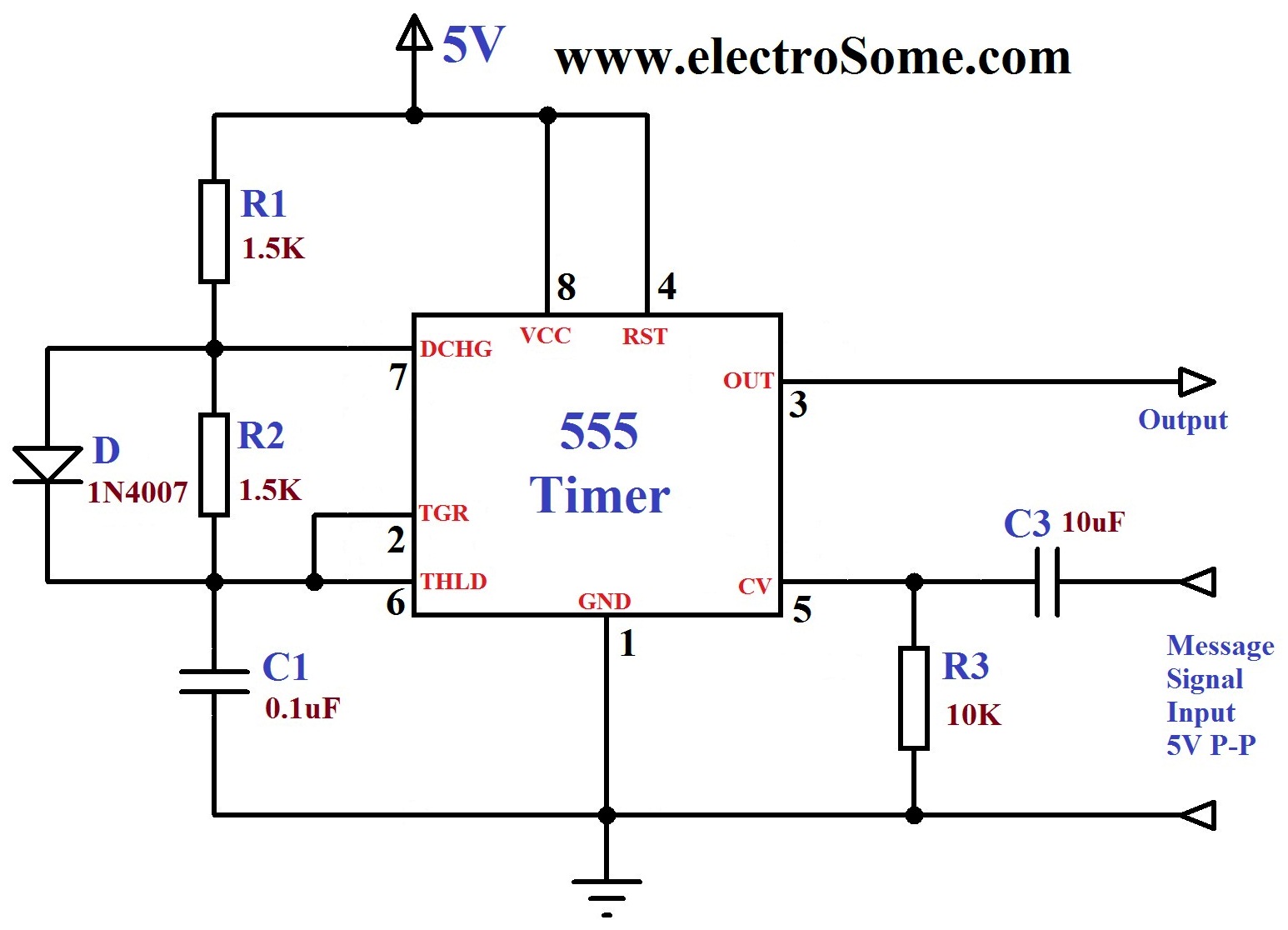
Astable Multivibrator using NE 555 timer IC -Circuit ...

555 Timer Basics - Monostable Mode

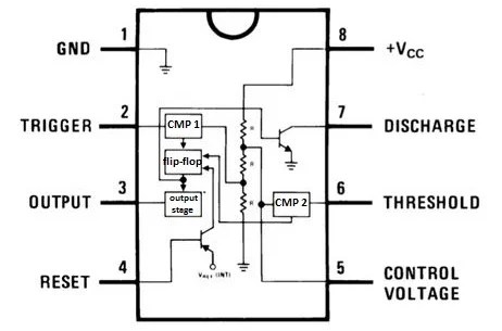
Timer 555 Schematic | IC schematics
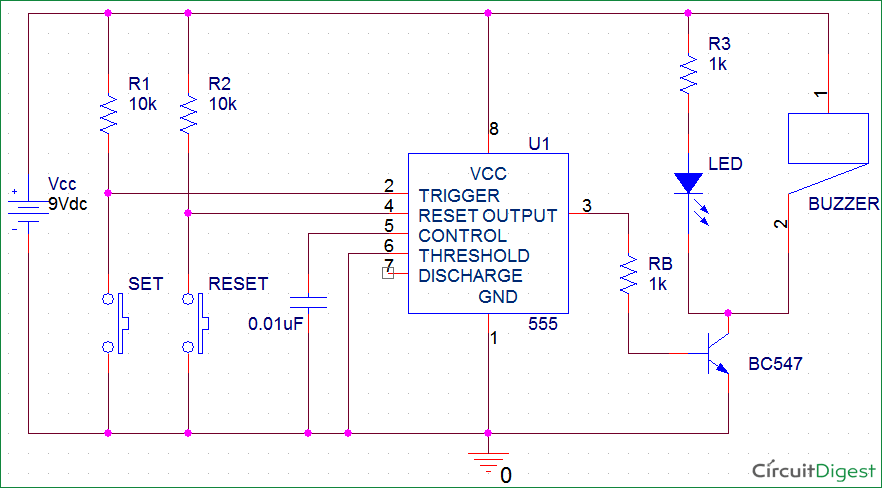
Panic Alarm Button Circuit using 555 Timer IC – ArRoboticsBlog

555 Timer IC Working Principle | The Simplest Circuit

555 Timer Delay Off Circuit Diagram | EEWeb Community
555 Timer Astable Multivibrator Circuit Diagram
You can watch the following video or read the written tutorial below. You can either follow the previous schematic or follow the breadboard wiring diagram below. Now a days many electronic components manufacturers produce it in large quantity.
